About Voltage Rating, Number of Turns Per Slot, Stands in Hand, etc.
- Background
- Specifications
- Making Compromises
- Let’s Face The Fact
- In FEA Modeling
- Okay, How to Configure Winding in Reality?
- This Whole Article is Wrong Because it is Based on a Wrong Premise
- Notes from Actual Doing It
Background
I am going to build a bearingless induction motor, and the next step is to wind the stator winding. I always found the winding the most irritating part during machine design. Therefore, this paper serves as a note how I managed to alter the winding arrangement of a theoretical design to that for an actual prototype.
Specifications
At the design stage, it is assumed that the voltage rating is 480 Vrms for this wye-connected 50 kW, 30,000 rpm motor. The parallel number of path/branch is 2 to enable a parallel no voltage combined stator winding setting [it requires more, e.g., on the number of slots $Q_s$ as multiple of 12 and the number of poles (cannot be 3)]. With a shear/tangential stress of 12 kPa, the rated stator current is 180.874 Arms. To achieve the rated power, the motor should be axially scaled to 281.2 mm.
The power stack (a nick name for inverter) we have is tested under 200 V dc bus voltage and 10 A ac or dc current. The Voltage rating for the switching device is 1200 V, which implies a highest output voltage somewhere below 600 V to make sure there is a safety factor for over-voltage (e.g., high dv/dt issue).
Please note that anything we say about rating is line-to-line value and we are considering a wye-connected machine, which means 480 Vrms is line-to-line voltage and $\frac{480}{\sqrt{3}}$ Vrms is the phase voltage.
Making Compromises
Considering all these, we are going to derive a design with (less than) 400 Vrms and 20 Arms from the theoretical design. Some compromises are made as follows.
- The maximal operating speed is reduced to 15,000 rpm. So the rated voltage is reduced to only half, i.e., 240 Vrms.
- The actual stack length for prototype is only 50 mm rather than 281.2 mm. Recall that the magnetic flux depends on the area of air gap surface, and back emf is proportional to magnetic flux, so the actual voltage rating is reduced to $240\times \frac{50}{281.2}=42.7$ Vrms.
- The current rating and voltage rating are interchangeable. In order to reduce the current rating by a factor of 9 (from 180 Arms to 20 Arms) , the voltage rating is multiplied by 9, equal to $42.7\times 9=384$ Vrms, which sounds good to me.
Let’s Face The Fact
It is almost not possible that the motor design from the analytical design procedure meets the 480 Vrms requirement with zero mismatch.
Okay, here is the part that is getting messy. Stay awake!
\[N=\frac{\sqrt{2} E_{m}}{\omega k_{w 1} \hat{\Phi}_{m}}=\frac{\sqrt{2} E_{m}}{\omega k_{w 1} \alpha_{i} \hat{B}_{\delta} \tau_{p} l^{\prime}} \Rightarrow \hat{B}_{\delta}=\frac{\sqrt{2} E_{m}}{\omega k_{w 1} \alpha_{i} N \tau_{p} l^{\prime}}\]where, the number of turns in series $N$ is determined by the back emf $E_m$, stator angular speed $\omega$, winding factor $k_{w1}$ and flux $\hat\Phi_m$ (a hat stands for amplitude). A quick detour: this equation is also used to re-determine the air gap flux density $\hat B_\delta$. We assume the voltage loss at rated operation point is 0.05 such that $E_m=0.95 U=0.95\times \frac{480}{\sqrt{3}} V$ and $\hat B_\delta=0.8$ T, and this gives us an $N$ of 6.08588, which rounds up to 6.
However, it is never that simple. You have to make sure $N$ is multiple of $pq=4$, because number of conductors per slot is
\[z_Q=\frac{aN}{pq}\]where $p=1$ is pole pair number and $q=Q_s/(2pm)$ the number of slot per phase per pole with $m=3$ and $Q_s=24$ the stator slot number. Let’s assume we got plenty voltage, so $N=8$. We use this new value of $N$ to calculate the new value of $\hat B_\delta=0.59$ T, such that the rated back EMF $E_m$ is still $0.95\times \frac{480}{\sqrt{3}}$ V. This means by increasing the voltage rating (and the thickness of stator insulation), we can build a less saturated motor. You can consider this as a trade-off between electrical loading and magnetic loading as well, I guess.
In FEA Modeling
What we have analyzed from the last section “let’s face the fact” has nothing to do with the FEA modeling. During (current source) FEA modeling, we need only the number of turns per slot $z_Q$ and current rating (180 Arms). So, what is this $z_Q$?
Please repeat after me. The correct name for $z_Q$ is the number of conductors per slot. The correct name for $z_Q$ is the number of conductors per slot. The correct name for $z_Q$ is the number of conductors per slot. It is not the number of turns per slot!!! And it is computed as follows (with an $a$ the number of parallel branch!)
According to Pyrhonen’s book, $z_Q$ is an integer or an even integer for double layer winding. This statement implies that during FEA simulation of a no voltage combined winding, the right turn number you should set to your FEM coil component should be $z_Q/2$.
The key take-away here lies in the name of $z_Q$. If the name of $z_Q$ is the number of turns per slot, which is not, it will be independent on the number of parallel branch $a$. With the correct definition, $z_Q$ is dependent on $a$, because $N$ has nothing to do with $a$ and $N$ is determined by the voltage we have. It is easy to get confused if you consider that you can reduce the number of turns in series $N$ by increasing the number of parallel branch $a$.
Okay, How to Configure Winding in Reality?
We haven’t covered how to reduce the current rating from 180 Arms to 20 Arms such that voltage rating is increased. However, this is quite straightforward. Just increase the number of turns in series and that’s it. In our case, the actual $N$ is $8\times9=72$.
In practice, we have to decide a wire gauge, e.g. gauge 20 or 21 (i.e., AWG 20 or 21?). In other words, we should use a proper strands in hand (多根并绕) to make sure a good fill factor (at least 0.4, or 0.45, and 0.5 by hand is already impressive, 0.7 can be reached using a automated robot and higher than 0.8 is possible by using a rectangle shaped wire (扁铜线).
However, owing to the reduction in current rating, we now have a quite high number of $N$ which gives a $z_Q=36$. This means that if we decide to use two strands in hand, there will be $72$ strands in one slot (please do not be confused about the concepts between turns and strands). If that’s too many for gauge 20 wire, then we should use gauge 21 or higher gauge to fit in the slot.
To this end, we have to compute the area of stator slot first. Here is a website showing you how to calculate the area of a polygon.
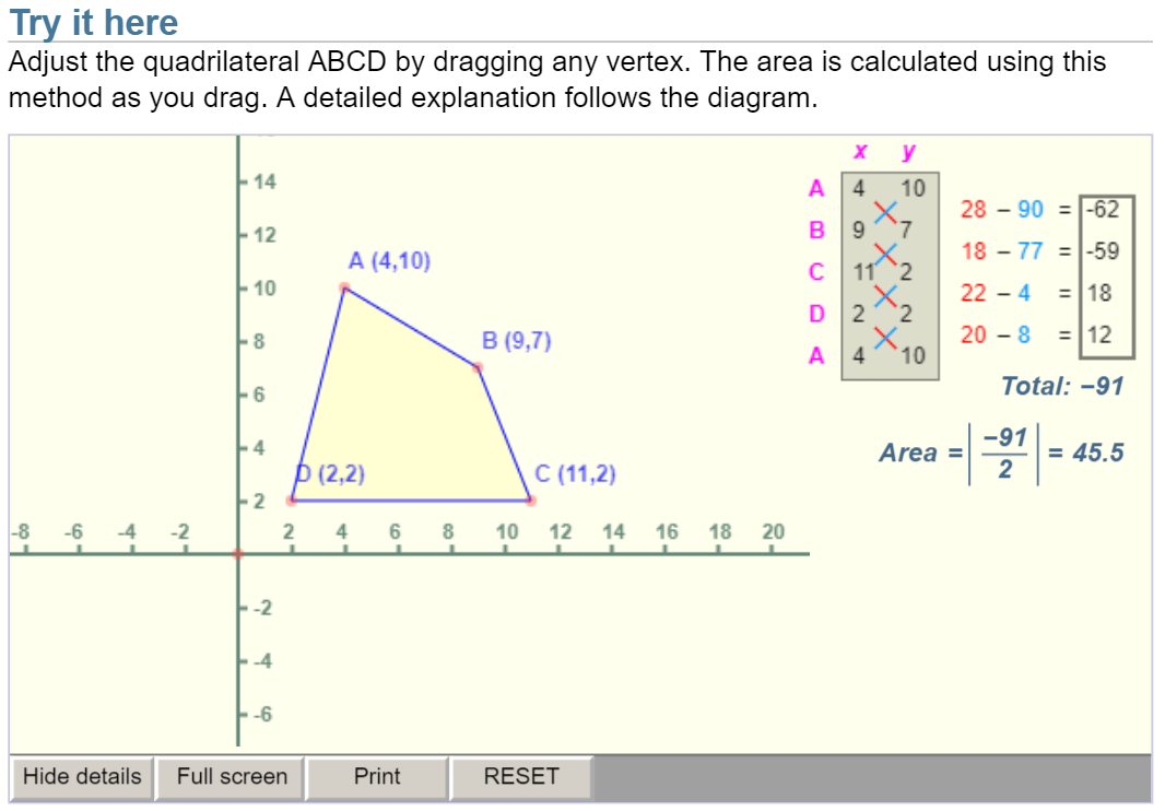
In case of 4 points, we have
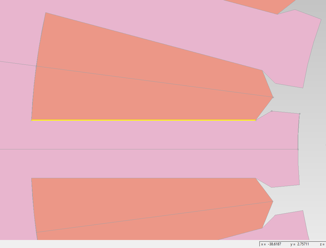
\[{\rm Area}=\left|\frac{\left(x_{1} y_{2}-y_{1} x_2\right)+\left(x_{2} y_{3}-y_{2} x_3\right) + \left(x_{3} y_{4}-y_{3} x_{4}\right) + \left(x_{4} y_{1}-y_{4} x_{1}\right)}{2}\right|\]The four points of our stator slot are respectively
-
-38.372, 2.6937
- -59.1465, 2.683
- -57.8252, 12.7074
- -37.76, 7.3315
This gives an area of 152.2 mm^2. Since we use a two layer short pitched (coil pitch is 75% of pole pitch) winding, the area for one phase conductors is only $\frac{152.2}{2}~{\rm mm^2}$. About short pitching, for a two pole motor, a coil pitch down to 70% can be used, as suggested by Prof. Pyrhonen in his book.
According to this site, a gauge 20 and 21 wire has a diameter of 0.81 mm and 0.72 mm, respectively. The corresponding area is 0.52 mm^2 and 0.42 mm^2. However, the actual space a wire occupies in theory depends on the what circular packing strategy you are using. We should now make some conservative estimation/predictions,
- using the fill factor, which gives $0.45 \times {152.2} {\rm~mm^2} / 0.52 {\rm~mm^2} \approx 132$.
- or assuming the wire takes space as a square wire of $0.656~{\rm mm^2}$, which gives ${152.2}/0.656=232$.
As a result, we will use 4 strands in hand, so that there will be $z_Q\times 4=144$ (close to $132$) strands for both the upper and lower layer of one slot, which corresponds to a fill factor of $0.49 = 144 / (152.2/0.52)$. Note that when you do the winding, there will be only “$z_Q$ times 4 strands divided by 2 layers” ($=72$) strands in a slot for one phase winding.
If the fill factor of $0.49 = 144 / (152.2/0.52)$ is too high. We can reduce $z_Q$ by increasing the current rating from 20 A to 22.5 A such that $z_Q=32$. 144 - 4*4 = 128, which gives a fill factor below 0.45 as 0.437. Each strand has 128 / 2 layer / 4 strand = 16 strand.
Finally, I can wind the stator winding using the specifications, $z_Q=36$, 4 strands in hand, gauge 20 wire. After connecting some coils, there will be 4 independent coils (i.e., 8 terminals) for me to connect to the torque inverter and suspension inverter.
Another take-away is about scaling. People say that the rotatory machine is easily scaled, compared to linear machine or axial flux machine. However, one thing these people do not tell you or even know is that you have to reconfigure your winding after you change your stack length. The reason is simple. By changing the stack length, your air gap surface area is changed and your flux linkage and back emf will also vary. As a result, $N$ and $z_Q$ must be changed accordingly.
This Whole Article is Wrong Because it is Based on a Wrong Premise
The theoretical designed prototype has a voltage rating of 480 Vrms by assuming the air gap flux density to be 0.6 T. What if the simulated air gap flux density is higher than 0.6 T?
Beginning of Detour.
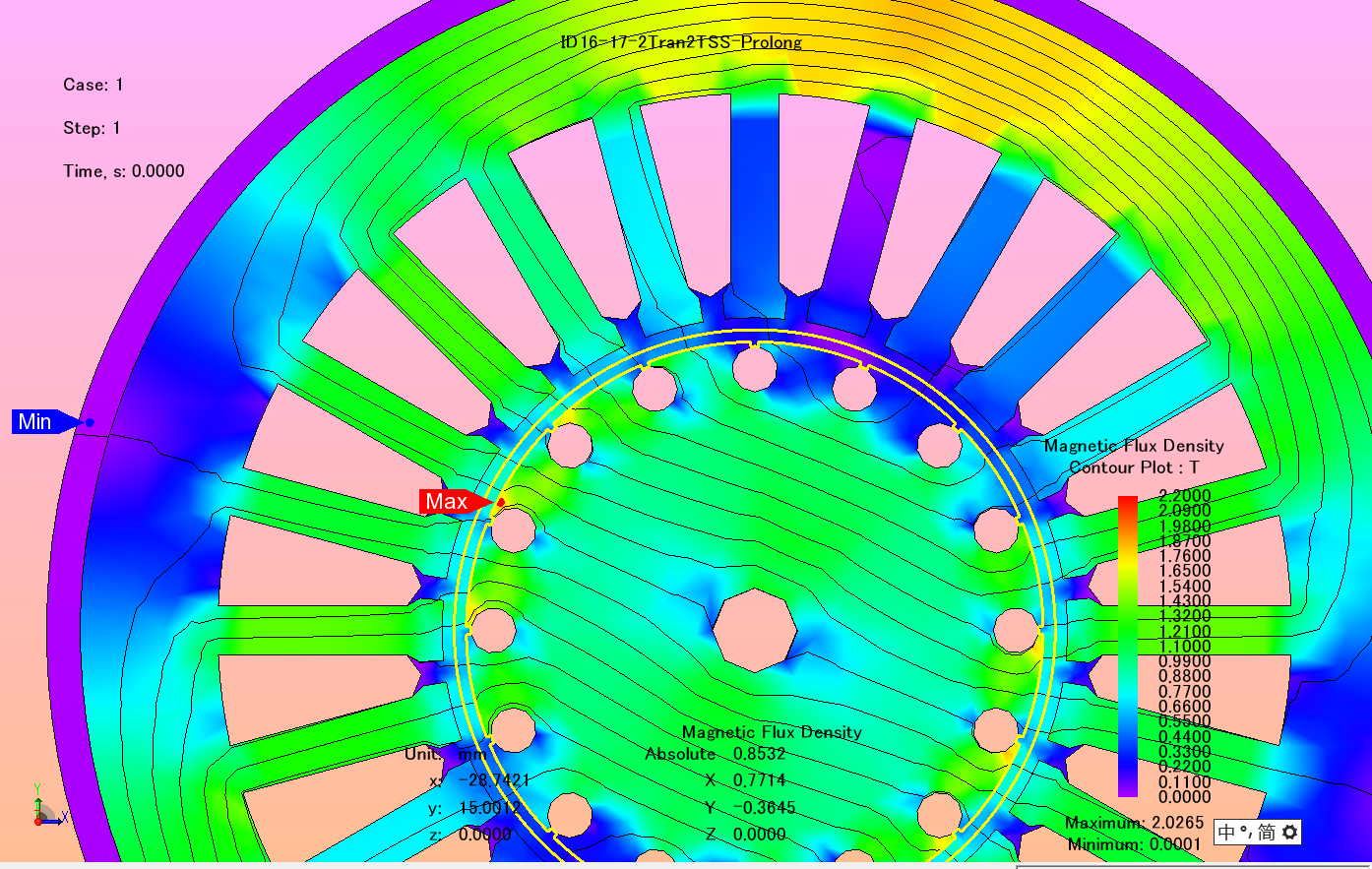
Okay, here, let’s make a mistake as an example. Take a look at the figure below, the turns of a coil is correctly set to $2=z_q/2$, where /2 means double layer. What will happen if we set this to $4=z_Q$? This is a common mistake I believe newbie may make.
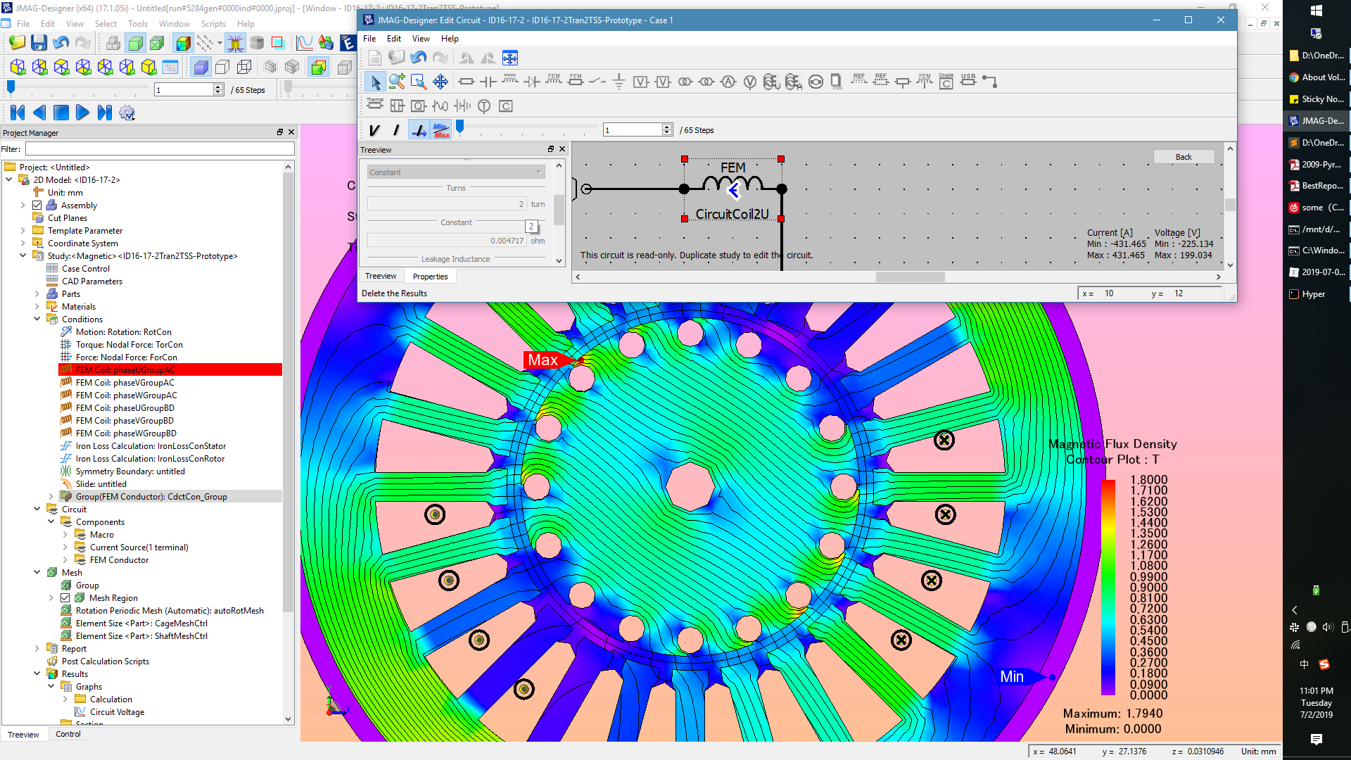
The consequence is that, according to the FEA analysis, this air gap flux density value is 0.85 T > 0.6 T. This is difficult to debug because newbie may think that the prototype design is suggested from the results of optimization, who is basically a bastard so its last name can be either Snow or Sand according to the birth place. In other words, he believes it is normal that the air gap flux density can be different than 0.6 T.
As a result, the induced voltage is way larger than 480/1.732 Vrms.

Damn it!
The thing is, the newbie cannot simply reduce $N$ because $N$ must be multiple of $pq$. So the only thing this poor newbie can do is to making compromises AGAIN. Re-design is not okay because the lamination of the prototype is already cut.
End of Detour.
Even if you make correct setting, you will not get exactly phase voltage of 480/1.732 Vrms. In our case, the phase voltage is 260 Vrms, which corresponds to line-to-line voltage of 450 Vrms. Okay, that’s fine.
Notes from Actual Doing It
- How to set up a lining paper
- Video from Youtube: https://www.youtube.com/watch?v=yPwf3BwS4pg
Leave a comment